Before your attention flags, I want to wrap up the hardware portion of this series and move into the software. But first I need to cover some odds and ends.
Marquee
Designing & Printing
At first I had no plans whatsoever for the marquee. I figured I’d install a solid piece of wood or MDF as the marquee’s façade and apply some sort of simple design on the front via painting or adhesive or something.
I’m not quite sure what made me change my mind, but eventually I found myself waist‐deep in Photoshop and Illustrator and googling things like “cartoon space explosion effect.” I spent most of my idle time over a weekend in Photoshop to come up with this:

Arcade enthusiasts, I’ve discovered, will have arguments about nearly anything — bat‐top versus ball‐top joystick, which kind of microswitch has the best feel, whether using anything other than a CRT monitor is a sacrilege. But everyone seems to agree that GameOnGrafix is where you get your marquee printed.
I gave them a Photoshop file sized to the dimensions I needed. In about ten days I received a gorgeous marquee and two pieces of protective acrylic.
Brackets
My lack of planning meant that I had no idea how I was going to install the thing. I ordered a standard marquee retainer of the sort you’d see on a commercial arcade cabinet, but when it arrived I realized that it was meant for a much larger space than the one I had. The lips were far too big and would end up covering up at least a third of the artwork.
Undaunted, or perhaps only partially daunted, I whipped up a Plan B. I figured something simple could do the job of holding the marquee in place, but all the metal angles I found had equal lengths on either side of the corner. That’s not what I wanted. I wanted the lip to be as small as possible, but the other side needed to be longer so that I could secure it to the cabinet with screws.
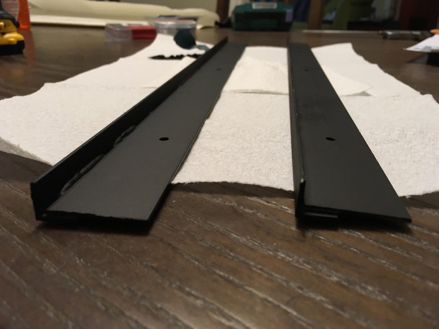
Since I wasn’t able to find something like this, I ended up getting one aluminum angle and one aluminum flat, cutting two pieces of the proper length from each one, then joining them together using JB Weld. Once they were joined, I drilled three holes in each one and spray‐painted them black.
From there it was straightforward: I screwed in the bottom bracket, sandwiched the marquee between the two pieces of acrylic, dropped it in, and installed the top bracket.
You’ll want the marquee to be pressed evenly against the front of the brackets. If this doesn’t happen on its own, drill some pilot holes into into the top and bottom edges of the MDF, the pieces above and below the marquee area. Insert a small screw in any place where the marquee is sagging. Tightening and loosening the screw as needed allows you to regulate the size of the gap.
Backlight
The GeekPub plans tell you to find a cheap fluorescent fixture at a hardware store. It seemed to me, though, that LEDs would be better suited for this task.
My approach was very similar to Bob’s approach in his tutorial:
- Cut a piece of MDF to the exact interior dimensions of your inner marquee area. Put some small blocks on the side walls of the marquee area at an appropriate depth. They’ll act as backstops.
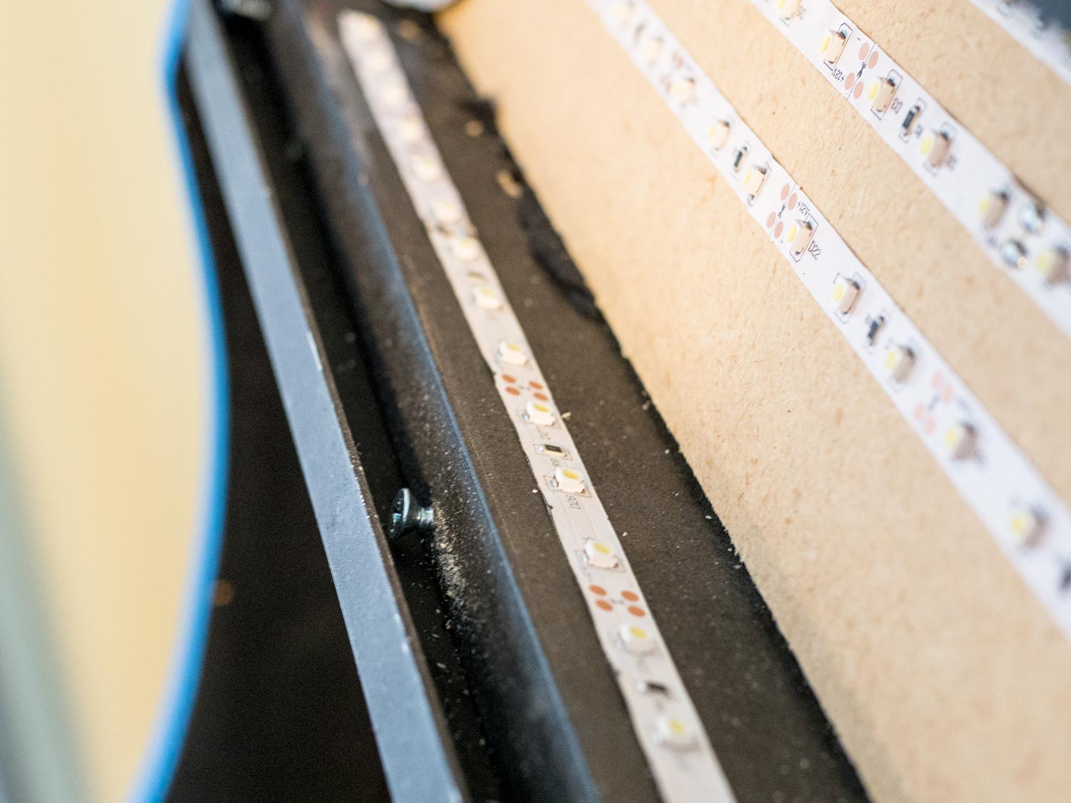
- Using a standard roll of 12v white LEDs, cut four or five strips slightly shorter than the width of the MDF. Adhere them in a zig‐zag fashion to the piece you cut in step 1.
- Join the strips by soldering small wires at the ends.
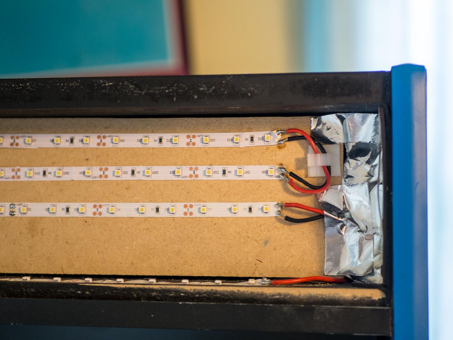
Once you’ve done this, you can place the MDF into the marquee recess and run power to the corner closest to where your LEDs begin. All that’s left is to plug the power brick into the outlets at the back of the cabinet.
Electricity
Shit! The outlets! I knew I’d forgotten something.
I want to strike the right balance here: on one hand, anything involving 120V AC power is to be taken seriously, and if you lack confidence, you should pay a professional.
On the other hand, installing this outlet was really, really easy. The Geek Pub’s video tutorial covers the basics, and if you want to investigate further, there are probably thousands of YouTube videos that show you how to wire an electrical outlet.

One tip: if you want something that feels sturdier than a wire nut, you can use these terminal blocks from Wago. They’re great for connecting wires together temporarily or permanently, and I’ve developed an unhealthy reliance on them.
The end result was a single three‐prong power cord that went into the rear of the cabinet and straight into a two‐gang electrical box with four outlets. From there I could power the Pi and the monitor.
Monitor
Shit! The monitor! I knew I’d forgotten something.
The Acer model from The Geek Pub’s plans suited my needs perfectly and is reasonably priced. (Good thing, too, because if I’d gone with a monitor of a different size, I would’ve needed to alter the plans.) It’s got a dumb “Acer” logo on the front, but a piece of black electrical tape will take care of that.
Stick a couple of long strips of scrap wood on either side of the cabinet interior at identical angles; they’ll act as backstops for the monitor. The panel in between the control panel and the monitor can be tricky to place, but my solution to that was to put some brackets on the ends with oval‐shaped, rather than circular, screw holes. That way I could screw the brackets loosely into the sides of the cabinet, then make adjustments as necessary before tightening it completely.

If you adhered to the plans closely enough, the monitor should fit perfectly — tight enough that friction will keep it in place, but not so tight that you’ll have to bang on it with a hammer to get it in.
The monitor came in handy in another serendipitous way. Raspberry Pis can output audio either via HDMI or via their analog jack. But the analog jack is known to produce an annoying hiss. Hence I was fortunate that the monitor also had an analog audio jack on the back; I could tell the Pi to output audio via HDMI, then rely on the monitor to pass the audio along to the speakers.
Speakers
Shit! The speakers! I knew I’d forgotten something.
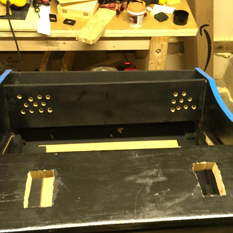
The plans tell you to drill a grid of small holes at the rear corners of the cabinet and to mount your speakers there. I wasn’t satisfied with this. Speakers belong just below the marquee, pointing down toward the screen and the player.
So this was what I’d do: I’d put the speakers in the empty space behind the marquee and point them downward. (Of course, this was before I decided to go with a proper marquee, but at least I’d had the foresight to mount them pretty deep.)

Barbara shops at craft stores pretty regularly, so I asked her to keep an eye out for speaker mesh — which she did, because she’s awesome. Using mesh meant I didn’t have to be obsessive about drilling perfectly spaced holes, since it was all going to be covered with cloth anyway. You might’ve noticed how slapdash my holes were from an earlier photo.
So the speakers got installed with some hot glue, one on each side. They’re powered over USB and the analog jack doesn’t have far to travel to reach the audio socket in the back of the monitor.
USB Hub
If you do everything the way I’ve done it, somehow the four USB ports on the Pi won’t be enough. But even if it had more ports, it wouldn’t be a great idea to rely on the Pi alone to power the speakers and the I‐Pac and the PacDrive.
Get a powered USB hub and put it somewhere near the Pi. Depending on your power needs, you may even be able to “backfeed” the Pi by powering it from that self‐same hub along with all your other stuff. Consult this list of USB hubs. Some work for backfeeding and some don’t; the “Powers Raspberry Pi” column is the one to check if you’re interested in backfeeding. This Plugable USB 2.0 Hub is one of the known good ones. (Don’t buy a USB 3.0 hub: they’re more expensive, certain USB 3 chipsets have known conflicts with the Pi, and the Pi doesn’t even do USB 3 yet, so there’s no point.)
The Pi
Now the brain. The inside of the cabinet seems cavernous at first, so you may think it doesn’t matter where the Pi goes. An hour later, when your wires are going in all directions, you’ll reconsider. So just save that hour and plan out where everything is going to go ahead of time.
My all‐time #1 beef with the Pi is that every orientation you put it in feels wrong when you’re trying to do cable management. If you use GPIO, as we will later on, you’ll have wires protruding out of four of the Pi’s six faces.
Here’s my advice:
- Get a case for your Pi if you don’t have one already. The bottom of the case should be a solid surface that we can put mounting tape on. The top of the case should be removable or should give you a no‐hassle way of getting to the GPIO pins; we’ll be using them later on.
- Use Velcro tape to mount it on the side of the cabinet. Anything more permanent and you’ll regret it the first time you need to take it down to check something.
- Do the same thing with the USB hub. Mount it on the same side as the Pi.
Aside: cable management
Just like with the control panel, the more obsessive you are with cable management up front, the more grateful the future version of yourself will be. Any cable that plugs into either the Pi or the hub should be affixed to the wall about six inches from the connector.
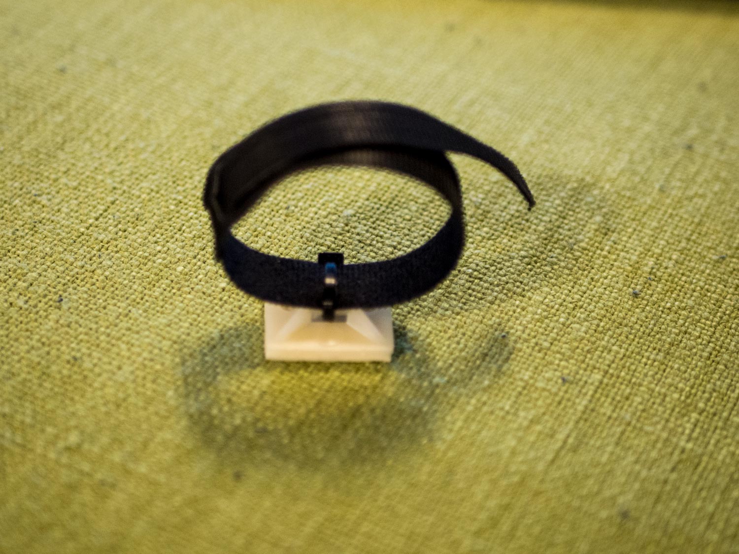
Here’s a recipe I’ve made at least fifty times in the last few years: start with one cable tie mount, loop a zip tie around it, stick a Velcro strap inside that loop, tighten the zip tie, and trim the excess.
You now have a way to affix an arbitrary number of wires to a vertical surface. Keep the velcro tie a bit loose while you’re moving stuff around, then tighten it when you’re done.
But why?
I want you to be this careful about cable management because the cabinet is nearly a literal black box. Because most of this won’t be visible, and because it seems like you’ve got plenty of space to work with, you will be tempted to slack off and just drape wires across one another. As soon as you do this, the die is cast. A week later you’ll be looking at a bowl of spaghetti.
Much like with cigarettes or heroin, you’re better off not starting than convincing yourself you can moderate your behavior. The goal is to have as few opportunities as possible for wires to cross over or under one another. As long as you do this, you will have plenty of space to work with.
This isn’t just about aesthetics. When you disconnect everything because you need to do something with the Pi, you’ll want to be able to reconnect it all without having to spelunk through a cave network of wires to trace everything back to its source.
Putting it all together
You can probably figure out what to connect where, but here’s a checklist in case you forget stuff:
- The USB hub gets power from a free outlet and plugs into one of the four USB ports on the Pi.
- The Pi gets its power from either a free outlet or the hub itself, provided you’ve got the spare amperage. (If you see a rainbow‐colored square in the corner of the display, that’s the Pi’s way of telling you that it needs more juice. If this happens to you, give up on your dream of backfeeding the Pi and just give it its own outlet.)
- The I‐Pac and PacDrive connect to the USB hub for power and for communication. (You can ignore the ServoStiks for now. We’ll get to them in a future installment.)
- The speakers connect to the USB hub for power and to the jack on the monitor for audio.
- The monitor plugs into a free power outlet. Connects to the Pi with an HDMI cable.
- If you’ve put the coin buttons in a place that’s detached from the control panel, like I have, you’ll need to remember to connect them to the control panel when you install it, preferably via some sort of long pigtail.
- The LED strip plugs into a 12v power supply, which plugs into a free outlet. (If you want the marquee to be lit up whenever the machine is plugged in, you can forgo a separate switch, but I’ve got one installed in the rear of the cabinet just because it was lying around.)
One more tip: label everything. Use a label‐maker if you have one; if not, use small loops of masking tape and a Sharpie. Wrap the labels around your cables near the ends. One label on each side of a cable isn’t the worst idea either. When you’re staring at four otherwise identical USB cables going into your hub, the labels will tell you what you should disconnect and what you shouldn’t.
What comes next
Now that we’ve got all the hardware provisionally set up, it would be nice if we had something installed on the Pi to prove everything works. I won’t hand‐hold you through the entire RetroPie setup process, but in Part Four I’ll tell you the stuff that I wish I’d known going in.
Comments