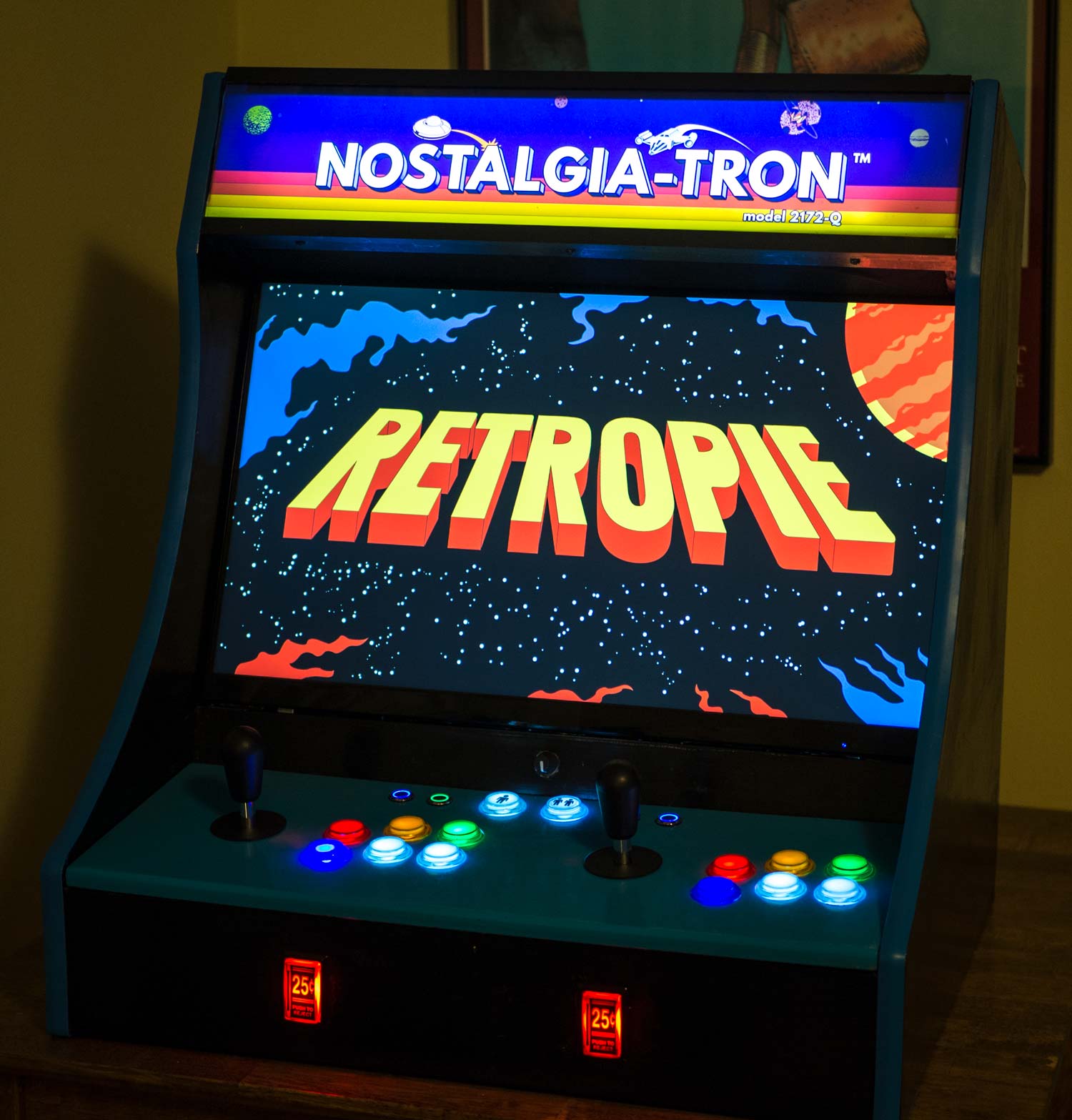
Last time I told you a story (without many pictures) of how I built an arcade cabinet out of a couple sheets of MDF. The part I left out was the making of the control panel — the MDF board that will hold the buttons, joysticks, and other controls.
The pieces
-
Two ServoStik joysticks. The ServoStik’s claim to fame is that it can automatically switch between 4‐way mode (very old games like Pac‐Man) and 8‐way mode.
Imagine a joystick in front of you. Pull it all the way down, then orbit it 360 degrees. The shape you trace will be determined by a restrictor plate on the underside of the stick. The ServoStik’s restrictor plate is shaped roughly like a square in 8‐way mode, thus allowing access to the diagonals; but in 4‐way mode, the plate is rotated 45 degrees, and the diamond shape means that the stick can’t travel to the corners. It rotates the plate with an attached servo motor.
-
A bunch of bog‐standard pushbuttons. Concave Happ‐style buttons are more authentic to the American arcade experience, but I prefer the convex style. I went with translucent buttons so that I could illuminate them with LEDs.
Each player gets six buttons in the standard Street Fighter II configuration. The first four buttons will be colored in the standard Neo‐Geo configuration: red, yellow, green, blue. Buttons five and six will be white.
The same style of button is used for Player 1 Start and Player 2 Start.
-
Four smaller buttons for some administrative functions. MAME, for example, maps “pause” to the P key on a keyboard. It’s easier to just map a physical button to P than to try to configure some weird button combo as a P‐equivalent thing.
-
All these controls will get wired to an I‐Pac. The I‐Pac acts as an intermediary between the buttons/joysticks and your computer. To the computer, it behaves like an ordinary keyboard, so it’s universally compatible. It’s got enough inputs for two players.
-
A PacDrive for LED control. Think of this like an I‐Pac but for LED management. Rather than have all my buttons light up at once, the PacDrive lets me control which buttons get lit up at which times.
My next machine — if there is one — will go basic: ordinary 8‐way joysticks and ordinary opaque buttons. The bells and whistles are nice, but headaches are not. And if this is your first cabinet project, as it was mine, consider going simple and straightforward.
The process
The photos in this section make it seem like I knew what I was doing here, but they don’t tell you that this was my fourth attempt at making the control panel. It’s not easy to fit controls for two players into a bartop form factor, and it took some trial and error to determine a button arrangement that was sufficiently comfortable for both players.
I also learned the hard way that the oil‐based polyurethane finish I had, which had given me no trouble on the cabinet itself, gave the control panel unsightly yellow streaks. I switched to a different finish on attempts three and four.
Making the panel

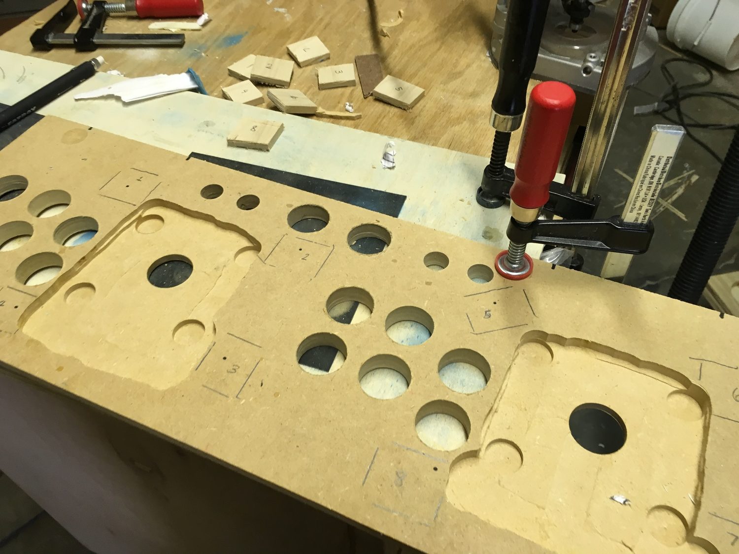
Much like my earlier process with cutting out the coin slot holes, I laid out a template in Photoshop, printed it out, trimmed it to exact dimensions, taped it together, and then adhered it to my MDF with Super 77 adhesive spray. A light spritz is enough to adhere the template to the MDF for drilling while also allowing for easy removal when you’re done.
Your standard arcade button is 30 millimeters in diameter, which is 1.18 inches, but the “trunk” of the button is slightly narrower. A 1⅛″ Forstner bit is the perfect size. I don’t have a drill press, so to ensure the bit didn’t wander on me, I first cut a 1⅛″ hole in a scrap piece of MDF, aligned that hole over the hole I wanted to drill, and clamped down the scrap.

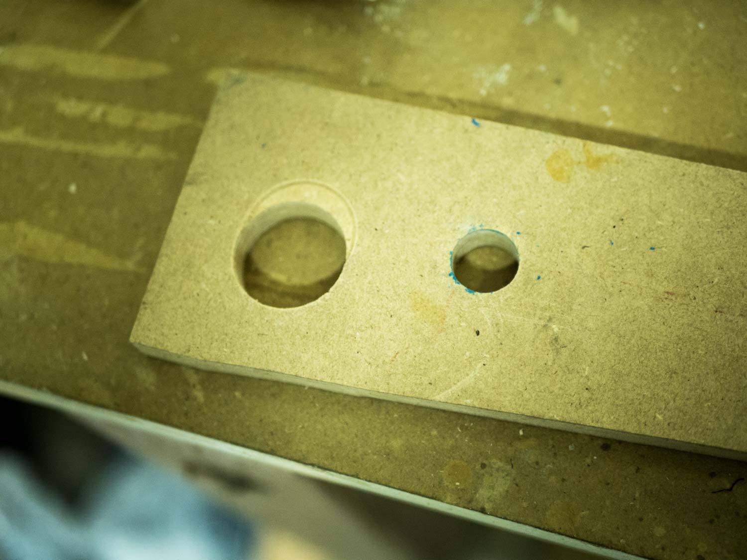
But by my third attempt, I realized that I could save some time. Forstner bits have a point in the center for gripping the material, so ordinarily you can’t use one to widen an existing hole — that point would have nothing to grab onto. But with my scrap piece doing the work of keeping the bit in place, I was able to go faster by first using my router to make ¾″ holes in the center of each circle.
With less material to cut, my Forstner bit was happier and drilled more quickly.
It’s common to finish the panel’s edge with more T‐molding, but I decided to round it off with my router instead.
The joysticks
A crucial puzzle to solve was how to attach the joysticks. I didn’t want any visible screw heads on the top of the panel. I also needed something durable enough to tolerate the desperate, panicky joystick flailing I do when I’m about to lose in a fighting game.
Yet many joysticks are designed to be mounted either from the top or from the underside of a very thin panel. They don’t envision a scenario like this, so I’d have to get creative. In the end, I used a technique I found while doing research — one which has worked flawlessly so far.
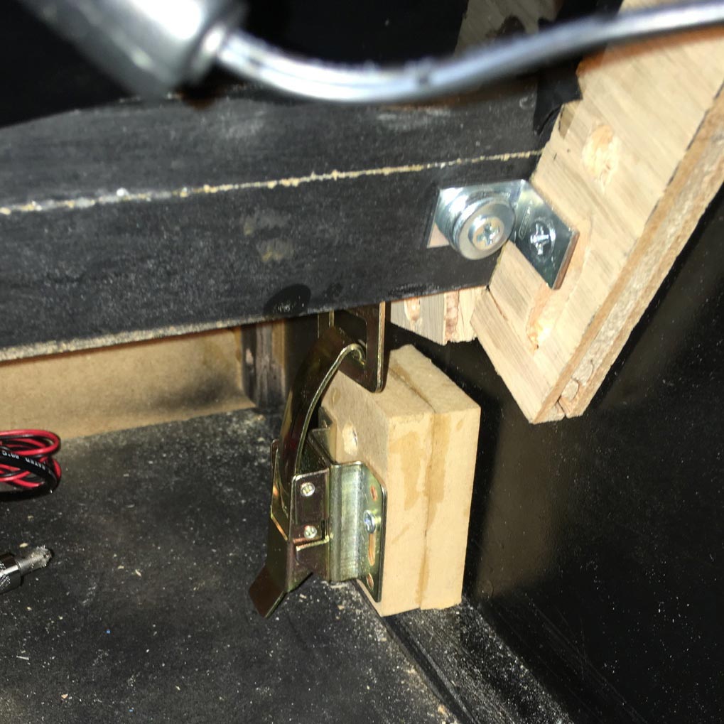
The mounting hardware for the joystick includes four “insert nuts” per stick. Drill a pilot hole a bit smaller than the nut and screw it in with a hex wrench; now you’ve got a place to screw a bolt into.
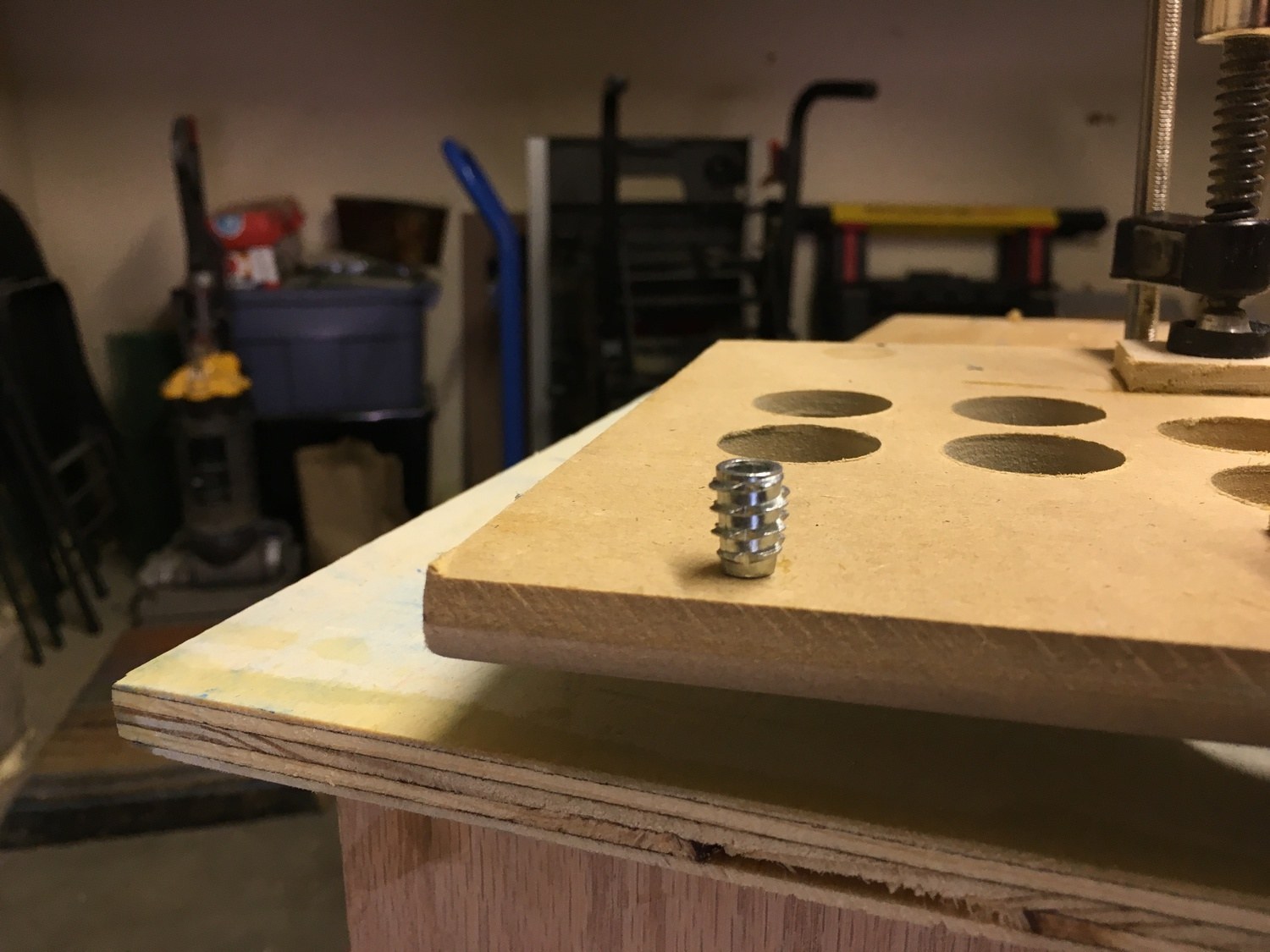
One problem, though: by themselves they were nearly as deep as the MDF itself. To install them I’d need to attach spacer blocks first.
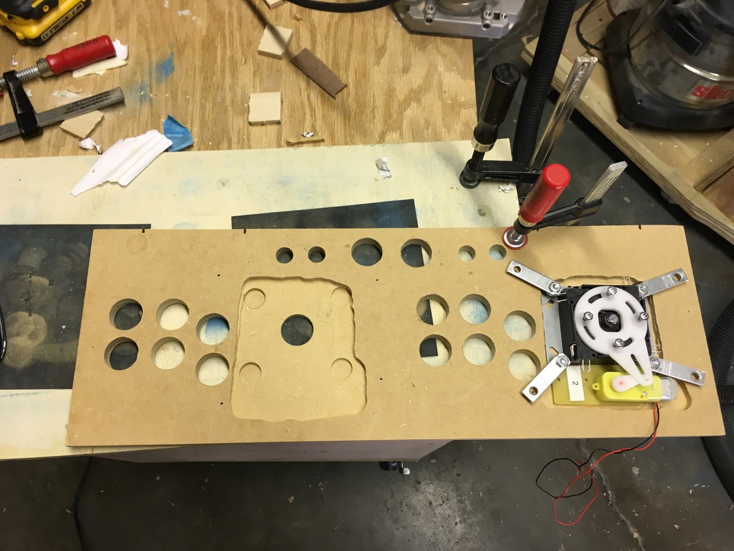
On the left side of this photo you can see how I routed out an area of the panel so that I could get the joystick closer to the surface. Then I routed four slightly deeper holes where the corners of the joystick’s faceplate would be; this was to leave room for the bolt heads.
On the right side of the same photo I’ve placed one of the joysticks in this well to make sure it fits, and to work out a way to place those metal bars so that they don’t obstruct anything else.
When I was done with this, I made pencil marks where the spacer blocks would go, then glued them to the panel with yellow wood glue. Once they were in place, I could install the insert nuts without worrying about them poking out of the top of the panel.
The end result is that the joystick is held in place by four metal braces that bind the four corners of the faceplate to the four holes made by the insert nuts. Underneath the metal braces are some washers that act as spacers to reconcile the depth difference between the two sides.
As I discovered, the best thing about this approach is that if you do everything else right, you can cheat and use three anchor points instead of four. This is what I ended up doing when I couldn’t find the eighth insert nut. I put the joystick through a stress test and found that even with only three anchors, it wasn’t wobbling at all.
A couple weeks into using the cabinet, however, I found that the nuts were loosening, presumably due to the repetitive motion of ordinary usage. I unbolted the bolts, spread some Loctite onto the threads, then bolted them back in. Everything’s stayed snug since then.
Sanity check
Once this was done — and before any painting took place — it was time to make sure that all the controls would fit as I intended.
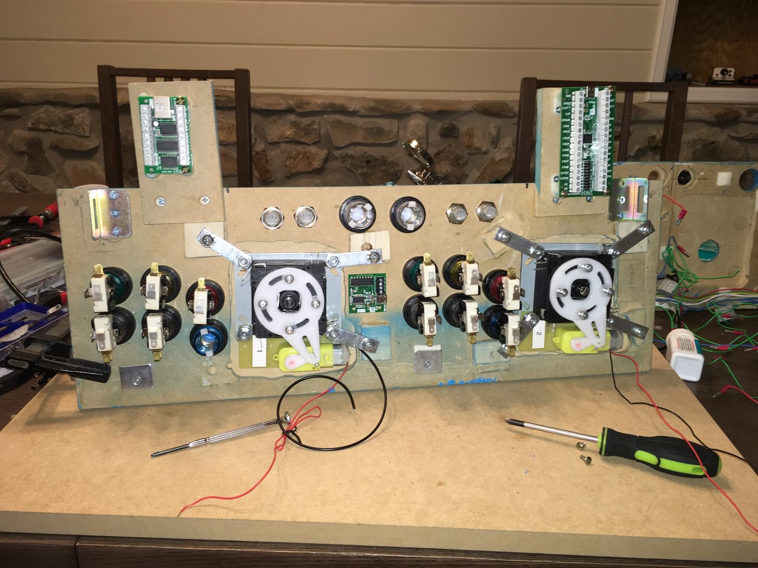
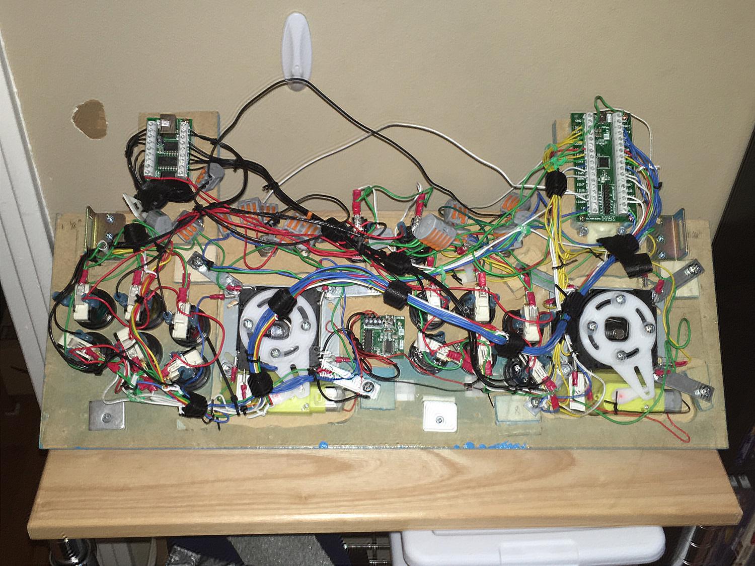
In this photo you can see the underside of the panel with all the hardware in place: eighteen buttons, two joysticks, two servo motors to toggle 4‐way/8‐way mode on the sticks, two brackets on the corners for securing the panel to the cabinet, and two MDF “extensions” for holding the I‐Pac and the PacDrive.
This wasn’t easy to fit on a tiny control panel. One alternative would’ve been to move the I‐Pac and PacDrive off of the control panel and mount them somewhere inside the cabinet, but my goal was to have as few things as possible tethering the control panel to the rest of the cabinet. If I want to remove the panel to do some troubleshooting, I don’t want to have to unscrew 28 wires. Better to unhook one USB cable.
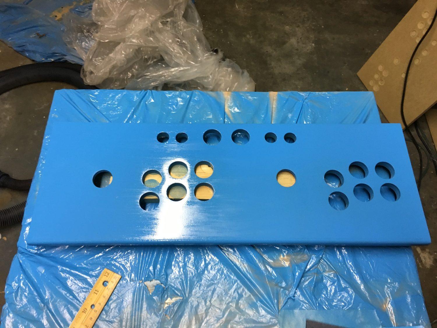
Now that I knew I could get all of this onto one panel, it was time to paint.
Painting the panel
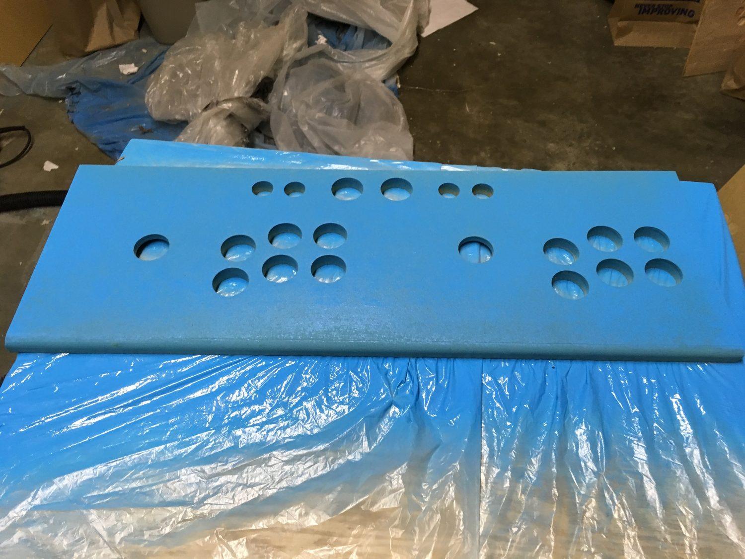
A thorough application of the random‐orbit sander made the surface super‐smooth. Several coats of spray paint followed. After the polyurethane lesson, I switched to polycrylic for the finish. I probably applied four or five coats with light sanding in between.
Installing the controls
Buttons
Screw‐in arcade buttons are easy to install; it’s a nut/bolt type thing. The button sits inside a plastic housing with a screw thread on the outside; a plastic ring is screwed onto it from underneath the panel until tight.
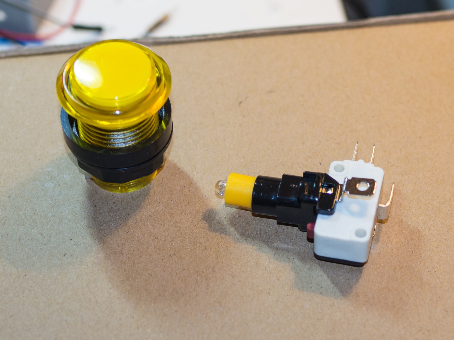
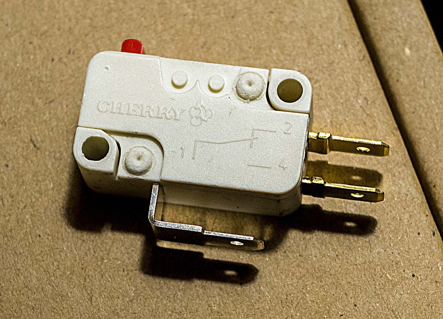
Arcade buttons use a common style of microswitch, and if you stumble into the wrong message board you can find pages upon pages of people arguing about which ones are the best.
Turns out that Cherry, the same company that makes the keyboard microswitches that dorks like me salivate over, also makes pushbutton microswitches in an arcade form factor. These manage to be pretty quiet without losing their clickiness.
It’s a bit odd if you think about it: all it’s doing here is making an electrical connection. But it’s modularized, plus components are larger than they strictly need to be so that they’re easier to use with human hands. Each arcade button is a miniature Rube Goldberg machine.
Wiring
The microswitch has three terminals: one for ground, one for “normally open,” and one for “normally closed.” The difference between these last two is whether you want the circuit to be completed when the button is pressed or when it isn’t. “Normally open” is what we need here.
(Most microswitches label these terminals as “NC” and “NO” — which is brilliant because those two strings look nearly identical when you’re trying to read tiny, low‐contrast text. Kudos!)
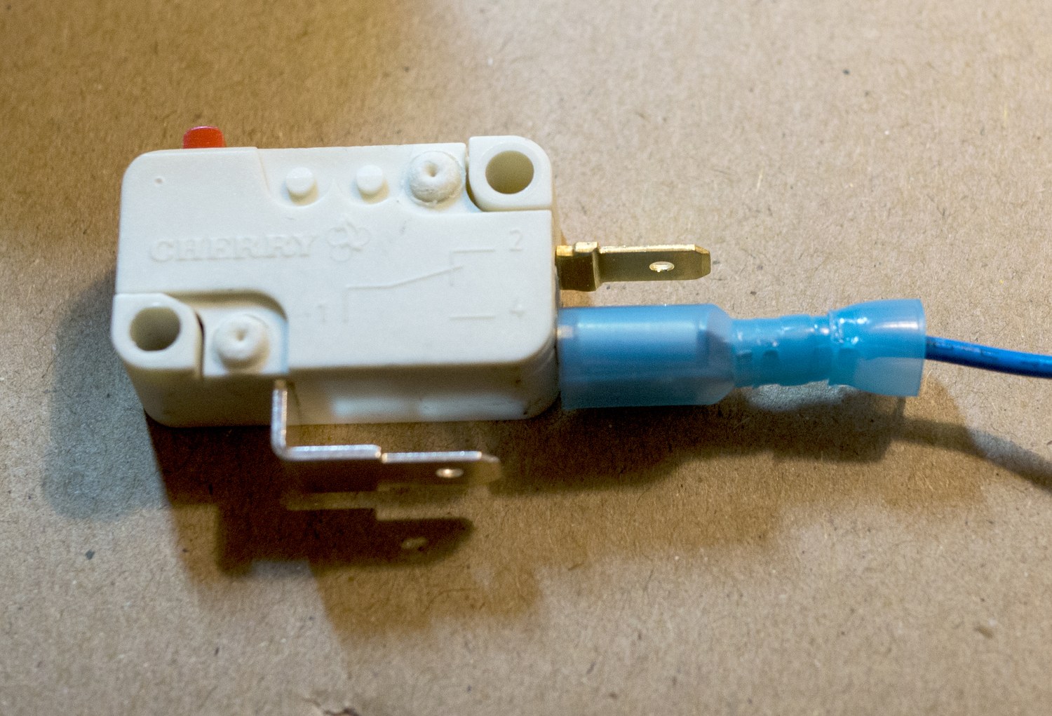
The terminals accept a common sort of connector that can be crimped onto the ends of wires. This is time‐consuming but ultimately worth it compared to buying a bundle of wires with connectors already attached. It means you can cut wires to the exact size you need.
The button’s housing also contains an LED. If you want to light them all up at once, you can daisy‐chain them like Christmas lights. But since I wanted granular control over which ones would be illuminated, only the common side got daisy‐chained; all the grounds went into separate terminals on the PacDrive.
Each button needed four connections, then. For input:
- One from an individual terminal on the I‐Pac to the “normally open” terminal on the microswitch
- One from the I‐Pac’s ground terminal to the microswitch’s ground terminal (daisy‐chained)
For illumination:
- One from the PacDrive’s 5V terminal to the LED’s positive terminal (daisy‐chained)
- One from an individual terminal on the PacDrive to the LED’s negative terminal
Lessons I learned
-
You want to use stranded wire rather than solid‐core wire. This is a no‐brainer decision if you know enough to realize the practical difference, but my lack of experience with hobby electronics meant that I started out with solid‐core wire for no particular reason. Solid‐core is far less flexible and is far more likely to sever a connection if the wire is bent too much.
-
Wire management is crucial. Though I didn’t sketch it out beforehand on paper, it would not be overkill to do so. The more colors of wire you have, the better. Use lots of wire clips to keep the wires running through the exact routes you define and for strain relief. Channel /r/cableporn.
You want enough slack in the wires so that the connection doesn’t get strained, but not so much that the excess can get tangled with other wires or hooked around something by accident. If you wind up with too much excess, loop up some of it and keep it in place with a twist‐tie.
-
Sanity‐check as often as possible. Don’t wire everything up and then test whether it works. Check after, like, two buttons at most. This is easy with an I‐Pac because you can just plug it into the nearest computer, open up a text document, and see if your button presses register the way keyboard input would. If you wait until the end, you’ll have a laundry list of things to fix.
-
The crimp‐on disconnects need to fit snugly onto the microswitches’ terminals. If you can disconnect one from its terminal just by poking at it, it’s not tight enough. If it’s not tight enough, you will be driven crazy when one disconnects at random at the slightest jostle.
Joysticks
Joysticks aren’t too different from buttons. They have four microswitches, one for each cardinal direction — when a joystick is moved to a corner, it activates two microswitches at once, and that has the effect of a diagonal.
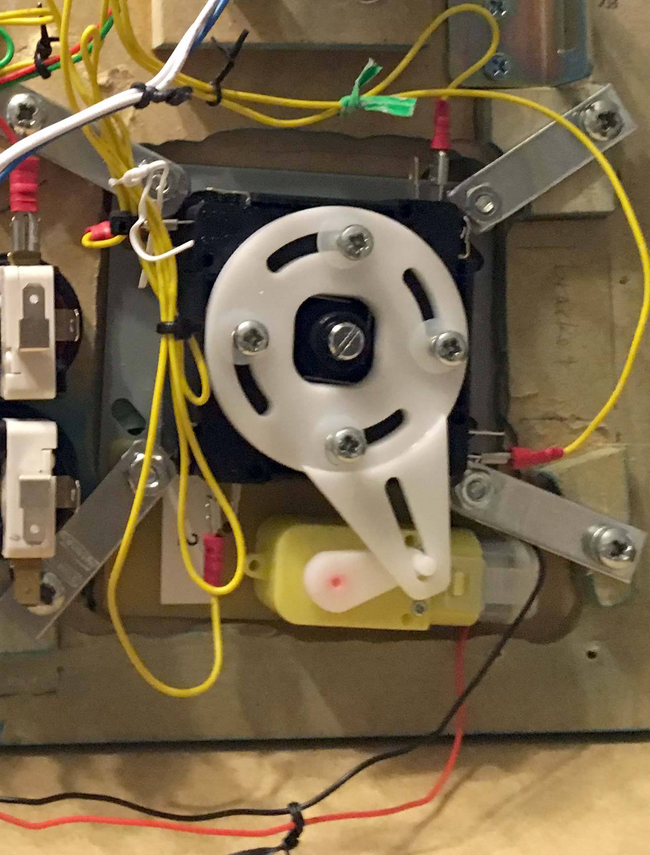
The servo motors had wires that needed to be screwed into terminals on a control board. This board then connects via USB to your switching mechanism of choice. Ultimarc makes it easy to switch between them in software from a Windows environment in which case you’d just plug the cable into your PC. But I’m not using Windows, so I decided to switch it into a “hardware” mode where I wire a USB cable into a physical toggle switch. (Later I realized I could do this via GPIO, making the toggle switch redundant.)
Putting it in place
The control panel has to sit in place no matter how badly I’m losing at NBA Jam. My first solution was to acquire a couple of toggle clamps, the kind that are typically used for full‐size arcade cabinets. I didn’t consider the fact that I’d have very little depth to work with — enough to get the clamps installed, but not enough to allow them to exert much downward tension on the panel. They should’ve been lower, but any lower and I wouldn’t have been able to clamp them shut.
I supplemented them with some magnetic cabinet catches on the front lip. Since the panel is angled slightly toward the player, I had to install the catches on the rear of the front panel at a similar angle. I used small pieces of foam mounting tape as a sort of shim on the lower half of the catch. Then I screwed metal plates into the panel itself.
This worked much better than I would’ve guessed — well enough to make the toggle clamps redundant. I usually leave them unclamped to no ill effect.
Connections
I did aim to minimize the number of connections that would have to be made between the control panel and things that weren’t on the panel. Here’s the list:
- One USB connection from the I‐Pac to the Pi.
- One USB connection from the PacDrive to the Pi.
- One USB connection from the ServoStiks’ control board to four GPIO pins on the Pi.
- Two connections to the coin slot buttons. Each of the two buttons on the front panel needs the same four wires described above. I was able to splice on some connectors to consolidate some of these connections, so the four wires coming out of each of those buttons are brought together into a four‐pin connector that connects to a corresponding pigtail on the control panel.
The end result
This is where I show you a photo of the completed wiring and you realize how much of a hypocrite I am.
Looking at this picture, it seems like I followed only about 50% of my own advice. But that’s why wire management is so important early on: the more diligent you are about it at the beginning, the better it will turn out even when you get weary and start taking shortcuts halfway through.
The moral
Punch your weight! It’s fine to want to deck out your cabinet. It’s fine to bite off a lot with your first project. But size your cabinet to match the size of your ambitions. Don’t be like me and try to stuff a bunch of cool shit into a sardine can, then whimper when it gets hard.
The good news is that the cool stuff we jammed into the control panel becomes less of a nuisance and more of an opportunity once we look at the software side. That’ll fill up an entire article later in this series.
Next time
Installing an illuminated marquee, wiring power, and placing stuff into the cabinet for the moment of truth.