My washer and dryer are two appliances that I’ve wanted to make “smart” for a long time, or at least smart enough to balance out how dumb I am about remembering to empty them when loads are finished. On several occasions, wet clothing has lingered in my washing machine for days. I’m not good at adult human life.
After I graduated from Arduino to ESP8266, my first project last year was also my most complex to date: detecting when a washer or dryer cycle has finished and sending a notification to my phone. Other people have had this idea, and by no means am I saying that this approach is the best, but it’s the first one I tried, and it’s worked wonderfully for me.
Now that I’ve got a few more projects under my belt, I felt like taking another swing at the laundry spy, so I’m documenting the process for revision 2. This is part one of another tedious multi‐part series!
Let’s talk about the hardware.
ESP8266
For the uninitiated: the ESP8266 is a microcontroller with built‐in WiFi made by Espressif. The work of some kind souls over the past couple of years means that the ESP8266 has been brought into the Arduino ecosystem. You can program it with the Arduino IDE or PlatformIO, and many libraries written for the Arduino will work with the ESP8266 with little or no modification.
As if that weren’t enough, the ESP8266 is also cheaper than most Arduinos. For less than the price of an Arduino Uno you can get an ESP8266 with built‐in voltage regulation and a USB interface.
Revision one of the Laundry Spy used an Adafruit HUZZAH. But my preferred board these days is NodeMCU; even the knock‐off versions are reliable, and can be programmed without holding down a button on reset. Three bucks each!
Accelerometers
How do we sense when the washer or dryer is in use? Several approaches will work. Current sensing? Damn near foolproof, but I don’t want to mess with 120V AC power. A photo resistor looking at an LED? Neither my washer nor my dryer lights up an LED during a cycle. The one I decided on is vibration detection. We can attach an accelerometer to each machine and read the force values several times per second; fluctuating force values signify vibration, and vibration signifies an active cycle. My washer and dryer vibrate like mad.
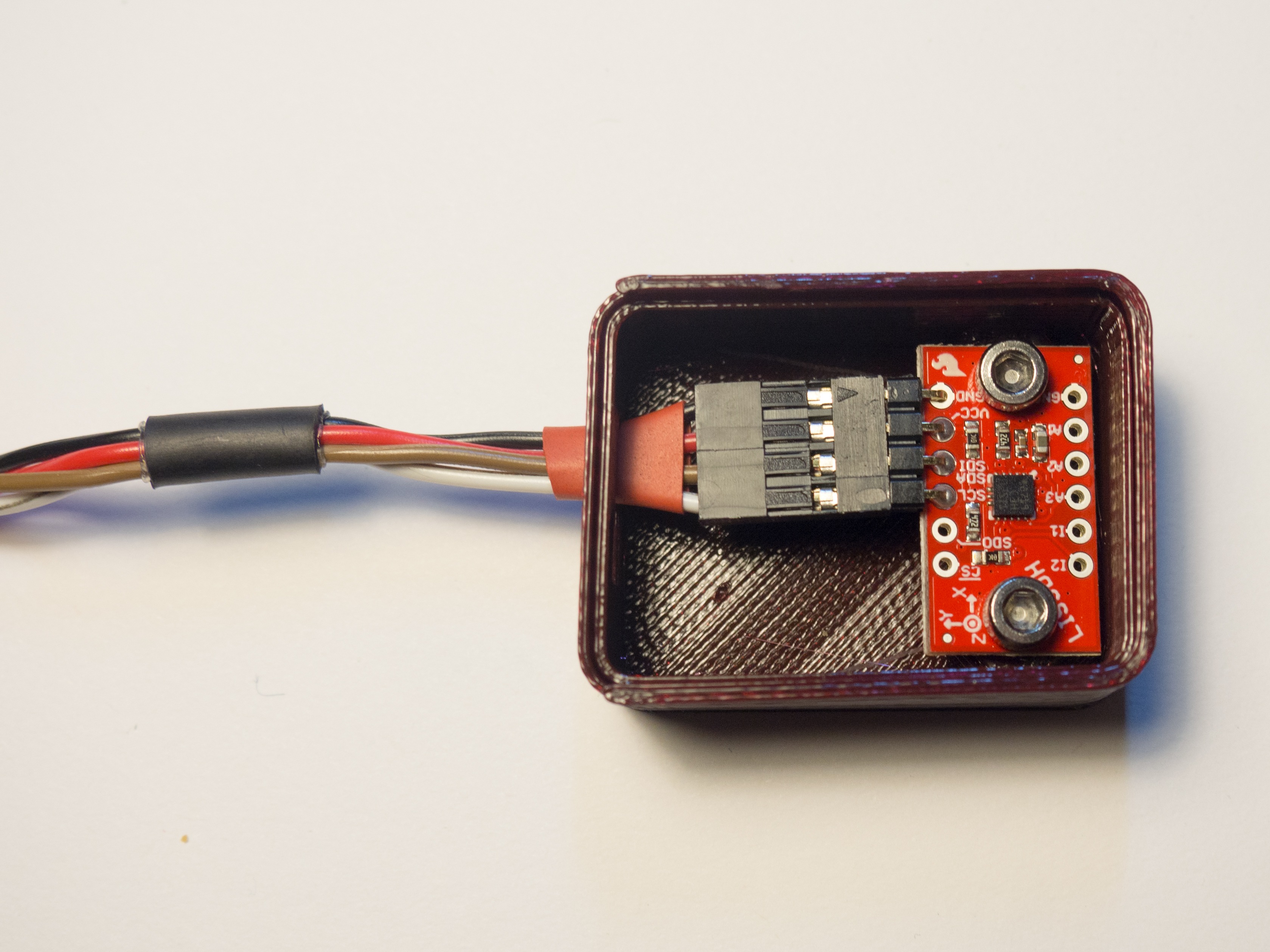
Revision one used the MMA8452Q accelerometer, but I went with the cheaper LIS3DH for revision two. You’ll need two of them — one for each machine.
Enclosures and wiring
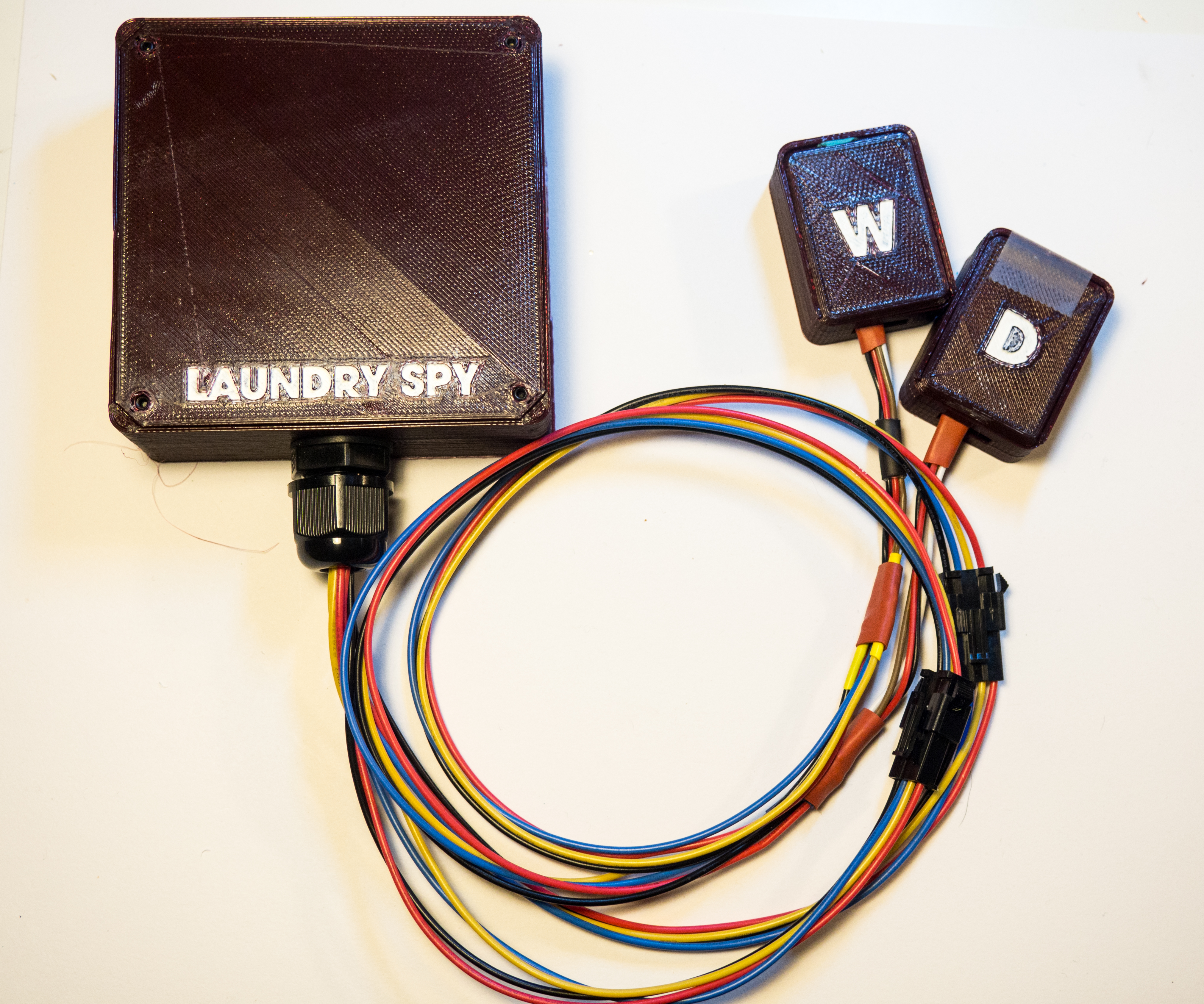
The ESP8266 will sit inside of a small 3D‐printed box. The accelerometers will sit inside two tiny cases, each one attached to the rear of its machine. We’ll connect them to the main unit via umbilical.
Each accelerometer needs four wires: ground, 3.3V, and 2 wires for I2C (SCL and SDA). These pairs of four‐wire pigtails are perfect for the task.
One important thing: the two accelerometers need unique addresses. Take one of the boards and solder together the two pads that determine which I2C address it’ll use.
Putting it together

Let’s start with the accelerometers. Each one gets four pins soldered onto it. Then join it to your pigtail by crimping Dupont connectors onto the bare wire ends. Or, if you’re as bad at crimping as I am, solder the wires together with some pre‐crimped wires like these, then add a four‐connector housing block onto the end.

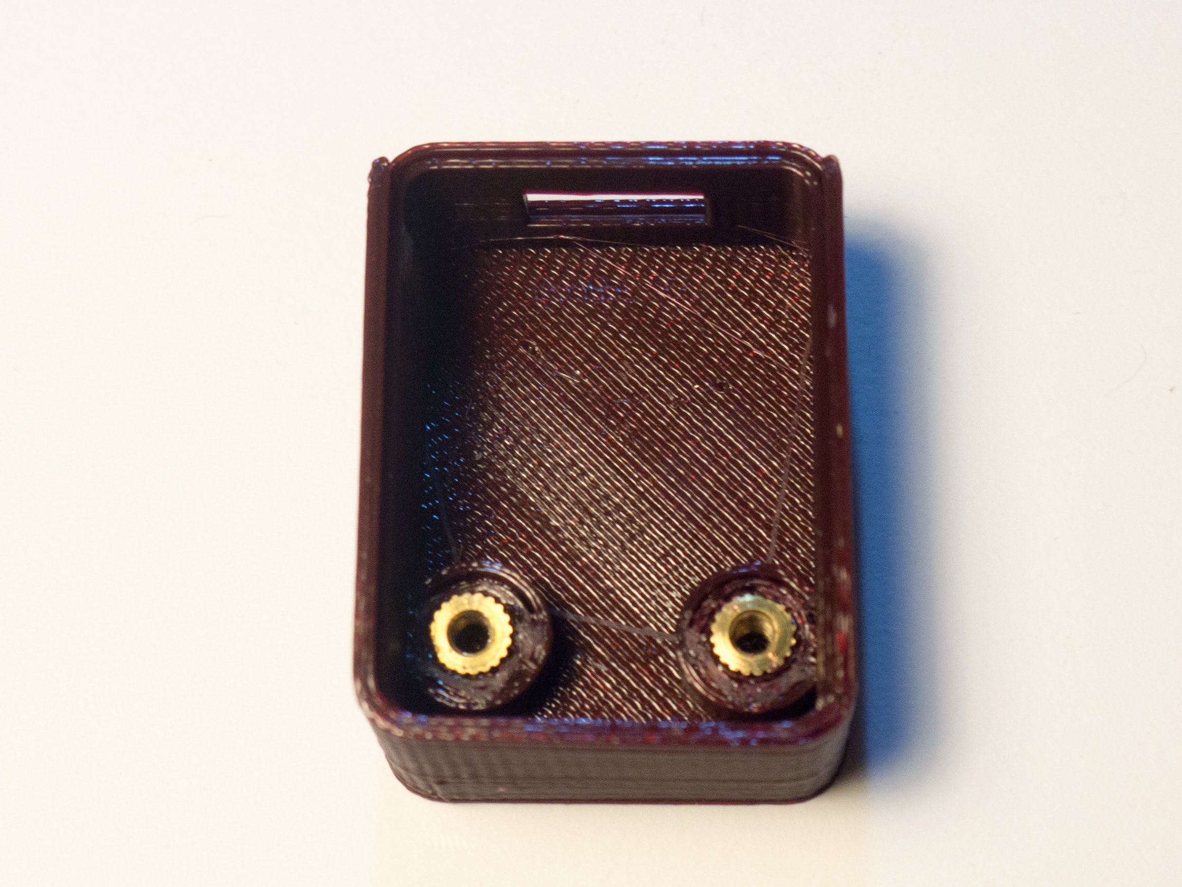
The accelerometer enclosures are adapted from this parametric box. We’ll get into my sloppy 3D‐printing methodology in another installment, but I’ll often start with someone else’s design, tweak it in OpenSCAD, then use TinkerCAD if I need to place some more complex features.
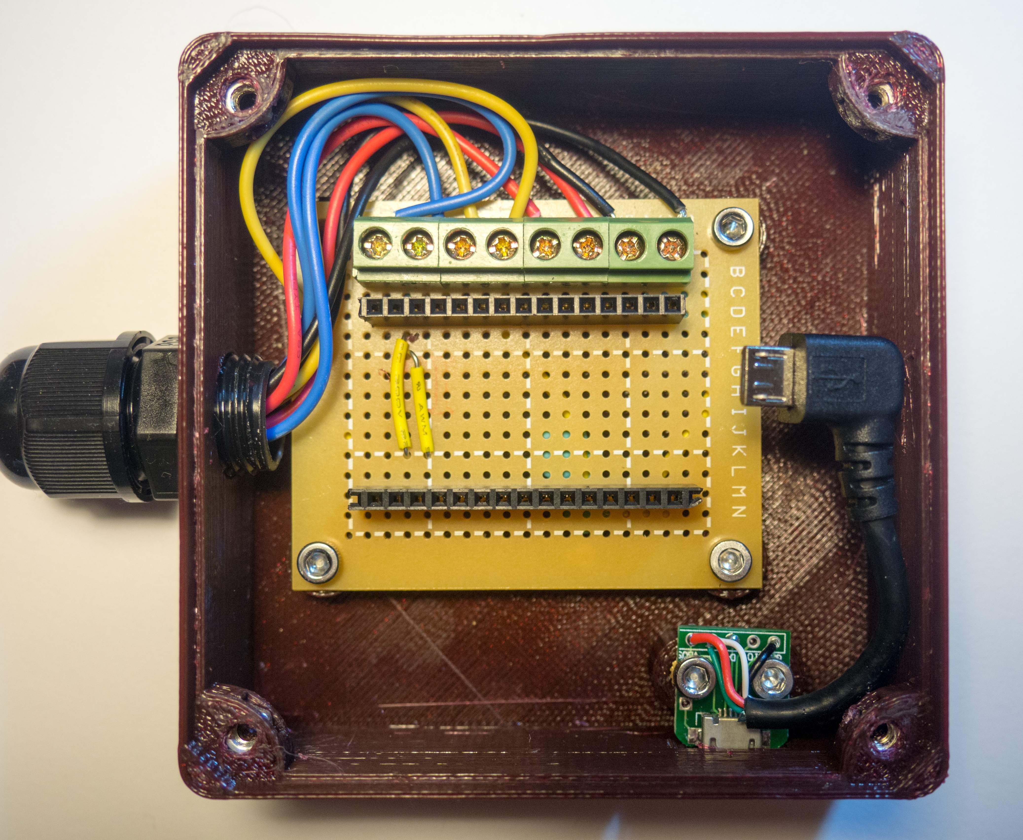
The ESP8266 sits in an ersatz socket on perfboard. We’ve got eight wires running into the head unit, so there are eight screw terminal blocks along one of the edges. On the bottom of the perfboard, we take each pair of terminal blocks and run it to the appropriate pin.

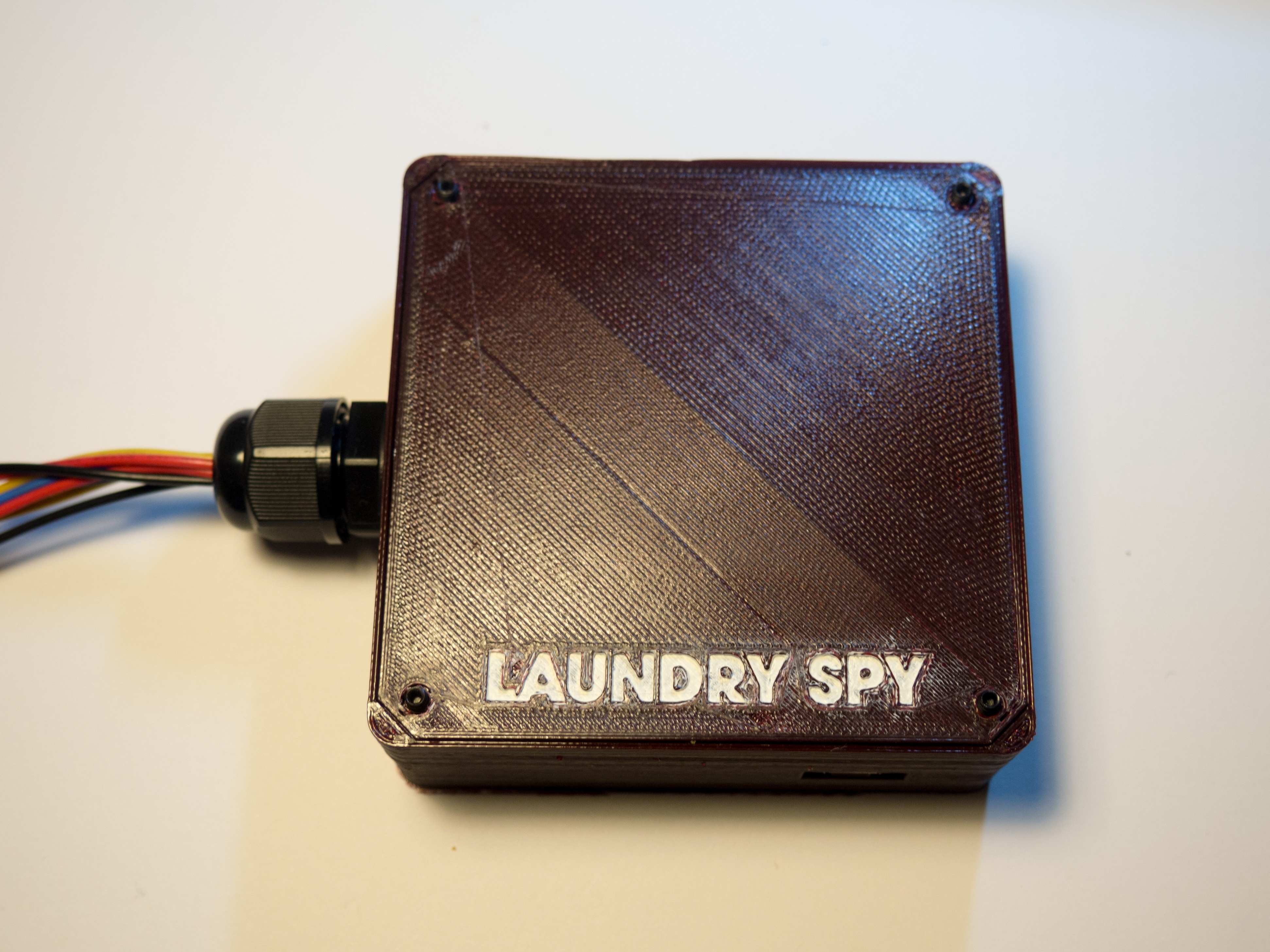
The perfboard is mounted into another 3D‐printed case based on another favorite design of mine from Thingiverse. I added text in OpenSCAD, recessed into the cover by a fraction of a millimeter; this lets me paint the letters into the cover later on by slathering some acrylic paint across the text and then wiping off any excess.
We’ll use a USB cable for power. I also want to be able to reprogram the MCU via USB if need be without taking it out of the case. I’ve got a bunch of these USB micro breakouts lying around; I like using them because it’s easier to incorporate it into a case design than it is to design the case so that the NodeMCU’s own USB port is accessible from the outside.
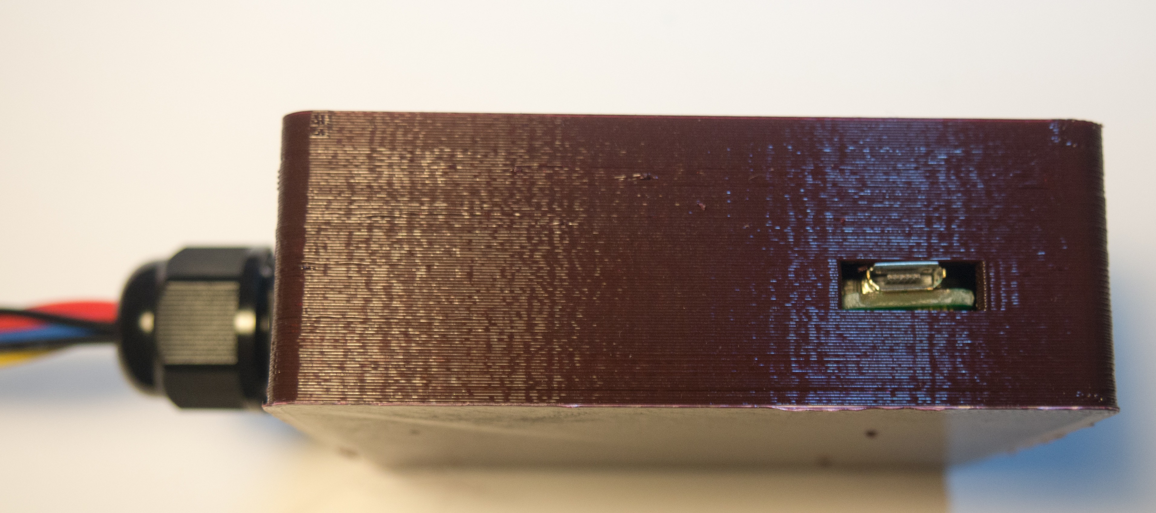
For strain relief, I used a cable gland because I had some lying around. But this is overkill; a zip tie or something similar will do.
The body of the case has nut traps at the corners. Put an M3 nut into each trap and you’ll be able to attach the cover to the body with M3 socket cap screws. If you’re careful and the contents of your box don’t exert any pressure on your cover, you can probably get away with M3 grub screws like I did; the lack of screw heads makes for a cleaner look.
Testing it
Break out your multimeter and put it in continuity test mode. Test each connection from the accelerometer to the MCU; if anything fails to beep, fix it now while all your enclosures are still open.
If everything works correctly, go drink a beer and wait for part two of the series.
Next time
Believe it or not, this was the easy part. Next we’ll figure out how to take raw force data and turn it into a laundry state machine. Part two will be exactly as exciting as I just made it sound.
Comments
:-)
Is there any chance of getting the STL files from the cases?
DouglasK